DIY Raspberry Pi Zero W 120v AC Outlet Controllers

Understatement
By Andrew Davidson
on August 17, 2018

shorturl:
w.undr.us/zerocontrol

I've been meaning to upgrade my beloved Lava Lamp Clock for over a decade, hoping to allow accurate network time, finite computer control, and less issues with Daylight Savings Time and power outages. After finding a slew of computer controlled AC power relay module projects posted online, I'd been collecting URL's for the eventual day when I'd make my own (well, three x eight outlets, really to cover the 24 hours). I'd also been slowly and surely buying the necessary parts required, and collected a box of stuff that needed to be built! Some of my earlier designs were based on a single Raspberry Pi B+ with a GPIO splitter to allow control over 3 distinct relays. With the invention and lower cost of the Raspberry Pi Zero WH ($14), I can afford to devote more processing power to this lowly task.

Finished Unit

Finished Unit

I don't like to be led around the internet with half-done tutorials that expect you'll fill in the blanks of glazed over instructions and lack of photographic evidence. This tutorial is my attempt at a start-to finish instructional tutorial to help you make your own. (Although I'll admit to guiltily not taking pictures toward the end...) If you are uncomfortable with household wiring and working with AC voltage, I suggest you don't do this project!

While you can attach your space heater, fridge and toaster oven to this, it's not designed for those types of loads. We've added a 10-amp breaker in-line to dissuade this type of use, as our plans call for each outlet to host a single 40 watt bulb, which only draws 0.36 Amps to operate, so even with a full load, is still under 3 amps.

Since there's a lot of standard elements being used in this project, anything suitably close can be substituted. In this case, I linked to the supplier I used (mostly Adafruit, Amazon and Home Depot) and the product I bought at the time, and the cost (partial costs, too), for a total cost of around $62 per unit. Having eight computer controlled (and therefore internet accessible) outlets would be welcome to anyone who's had to reboot a computer from miles away. This could also be the hardware base for any Christmas Light or Halloween decoration systems with some additional programming. Although my finished box is not weather-proof, you could try to seal it using a faceplate and beads of silicone on any open seems.

Parts List

  • (4) 15amp Dual-Plug 3-Prong Outlets [$5]
  • (1) 5v 8 Relay Module [$8]
  • (1) Raspberry Pi Zero WH [$14]
  • (1) 3" Premium Female/Female Jumper Wires [$4 ($1)]
  • (1) Raspberry Pi Zero Case with GPIO access [$5]
  • (1) 4GB Micro SD Card [$5] with Raspian Stretch Lite as a fresh install
  • (1) Small USB Power Supply 1A+ Output [$5]
  • (1) 3-6" USB Cable A > Micro A [$1]
  • (1) Sacrificial (long) 3-Prong Power Cord [$2]
  • (1) 10-amp Breaker (for Safety!) [$6]
  • (3-4') 14 gauge White & Black & Neutral Wire (Romex 14/2) [$12 ($2)]
  • (1) PVC 4-Gang 71 cu. in. Old Work Box [$7]
 

Software Build


Let's get started by doing the software install before we get out the wire cutters. Install your brand new Raspberry Pi into it's case, and insert your freshly copied Rasbian Stretch Lite micro SD card into it. You'll have to hook up a HDMI monitor and USB Keyboard (you'll need a USB Micro A Host adapter) to your Raspberry Pi as we have a lot of software and configuration to do. All of this can be done without it being added to the hardware we have yet to build. Once you're ready, plug it into the USB power supply and the wall - it should give you the rainbow screen, then boot like normal. After you login with the default account (pi / raspberry), you'll need to do some basic housekeeping.

sudo raspi-config

Go through all the options and set it up to work with your country, keyboard, language, wifi network, etc. I like to change the password on the default account, give a name to the computer, setup the wifi, turn on SSH access, then when you're finished it'll reboot. Remember the shortname of the computer (you'll be using this to access it on your network later). Currently, my versions join the local Wifi network, and can be accessed by shortname on the same subnet: lightblue.local, skyblue.local, and trueblue.local.

Once you're back up and logged in (it should have also joined your home wifi network, so you could feasibly continue via SSHing into the computer), do the generic Rasbian software updating (the trailing -y auto-accepts any changes): This might take a moment, and download some data; Let it finish.

sudo apt-get update -y
sudo apt-get upgrade -y

Install Wiring Pi

We're gonna download and build Wiring Pi (instructions) to control the Raspberry Pi's GPIO pins - this will let us turn on and off our Relays via web, cron, or API. First, we have to install GIT so we can build from source.

sudo apt-get install git-core
git clone git://git.drogon.net/wiringPi

Now we're gonna build WiringPi, first by moving into the directory, then running the build command.

cd wiringPi 
./build

After a while, it'll give you the go-ahead that's it done building, and now you can test our install by typing:

gpio -v 
gpio readall

Boot Reset GPIO

We're gonna reset all of our GPIO pins that we use on boot, to ensure that it acts fault-tolerant (computer rebooting will turn off every outlet). This requires adding some text to the file /etc/rc.local

sudo nano /etc/rc.local

Add the following lines to the bottom of the file, just before exit 0:

/usr/local/bin/gpio write 0 1
/usr/local/bin/gpio mode 0 out
/usr/local/bin/gpio write 1 1
/usr/local/bin/gpio mode 1 out
/usr/local/bin/gpio write 2 1
/usr/local/bin/gpio mode 2 out
/usr/local/bin/gpio write 3 1
/usr/local/bin/gpio mode 3 out
/usr/local/bin/gpio write 4 1
/usr/local/bin/gpio mode 4 out
/usr/local/bin/gpio write 5 1
/usr/local/bin/gpio mode 5 out
/usr/local/bin/gpio write 6 1
/usr/local/bin/gpio mode 6 out
/usr/local/bin/gpio write 7 1
/usr/local/bin/gpio mode 7 out

Sorry for all the typing, (easier if you're familiar with nano's tools) but save and exit nano. This will put the GPIO pins (and hence the relays) into a default position (1 being non-active) on boot-up, without having to open the web browser or access the device.

Install Web & PHP Server

We're gonna need to have the Raspberry Pi accept commands from the internet, so best start with a web server that can handle PHP files. Using this command gets you the lightweight lighttp web server and the minimum php libraries needed.

sudo apt-get install lighttpd php7.0-fpm php-cgi

After that's done, we have to enable the php module for lighttpd and restart the web server.

sudo lighttpd-enable-mod fastcgi-php
service lighttpd force-reload

If you browse the computer with a web browser (http://shortname.local) you should see the default web page. Now we need to copy some support files to the web server directory (/var/www/html/), to allow control via web browser. We'll be doing that with FTP by installing a FTP server.

Install FTP Server

There's plenty of options for FTP servers, and I followed this tutorial to get me started. We'll be installing Very Secure FTP:

sudo apt-get install vsftpd

We should edit the default configuration, and make it suitable for our use.

sudo nano /etc/vsftpd.conf

There's lots of options to page through, and you can turn them on or off by putting a # before the line (thereby making it ignored), as you can see from the prolific instructions inline. A few select changes that are recommended before you save and close the file:

anonymous_enable=NO
local_enable=YES
write_enable=YES

Since we'll be editting files in our web directory, and might require administrative control via FTP, we'll have to allow root to FTP into our server. From the command line:

sudo nano /etc/ftpusers

comment out the root user by adding a # prefix so the root line looks like this:

#root

Save file via nano, then close and then restart the vsFTP server

sudo service vsftpd restart

Install Web Control

We'll be using the Simple And Intuitive Web Interface code we linked to at the bottom, as it's a great start and requires little effort to install (why reinvent the wheel?). Download the Web 2.0.zip file to your local computer. Unzip the archive, and use your brand new FTP server to copy the files to your pi home folder (you'll only have permission to upload here anyway), then you can move them to the public web directory via sudo.

sudo mv /home/pi/data/ /var/www/html/data/
sudo mv /home/pi/script.js /var/www/html/script.js
sudo mv /home/pi/gpio.php /var/www/html/gpio.php
sudo mv /home/pi/index.php /var/www/html/index.php

This solves most permission and execution issues, and the code should just run when you refresh your web browser (http://shortname.local)

Add Shutdown Script

This will allow us to safely shutdown the Raspberry Pi inside to allow safe unplugging. I imagine continuous hard resets by losing power suddenly will eventually tax the poor SD Card, and since it's so hard to extract and replace, we might as well treat it nicely. While it's an extra effort, you can still unplug the power strip while it's in use and expect it'll boot fine next time.

sudo visudo

Add the following line at bottom, this will allow the web server to run the shutdown command without requiring a password.

www-data ALL=NOPASSWD: /sbin/shutdown

Next, we'll create a PHP page that does the execution. With this line, we're both creating and editting the shutdown.php file with one line.

sudo nano /var/www/html/shutdown.php

In nano, the absolute minimum contents of the shutdown.php file should be:

<?php system('sudo /sbin/shutdown -h now'); ?>

You can add a link to this page anywhere on your controller page for safe power-downs.

sudo nano /var/www/html/index.php

While I was editing the HTML file, I made some color and size changes along with adding HTML tags and other stuff to help define each unit, as I was making 3 of these in a row, and they can't all be named the same and have exactly the same look of each web page. You can add some complex HTML5 behaviors here to make this act more like an app than a web page!

Make a backup of your SD Card

You can follow my instructions from years ago on how to make a backup of your SD Card onto your desktop computer, so you can generate new copies easily, and keep a backup offsite in case of disaster. As I was making three of exactly the same units, I copied it onto several cards and used them repeatedly! I booted each Raspberry Pi once and ran raspi-config to change the computer name and alter the HTML files to reflect it.


Hardware Build

Pulling Common Hot Jumpers

Let's get to the wiring! We need to prep the four 2-gang outlets; since each outlet will be switched individually, while we can group the neutrals (white), each hot (black) lead needs to go to a single receptacle. This means using needle-nose pliers to snap the common tab on the gold (hot) side. You'll need to grasp them securely and bend them back and forth until they break off. This step allows the top and bottom to operate independently.

4 outlets Bonded Neutral

I prefer to work with dead-bug prototypes, with compact hand wiring. Since we'll eventually be mounting all 4 outlets in the 4-gang work box, we can set them on top, face down so we can approximate their final placement, and cut wires that are just to length.

As seen in the picture, we've bonded all the neutral (white) sides of all four outlets, and even have a pigtail (which we eventually discarded). There is a slight bend in each wire to allow flexibility when being re-seated into the PVC Work Box.

Neutral, 8 Hots, and Bonded Ground

After that, we used a longer piece of unshielded ground wire to group all 4 of the grounds on each outlet and leave another pigtail for the incoming ground.

Then, we cut eight pieces of black hot wire, and stripped one end and wired each individual circuit to it's own hot lead.

Still considering the size of it's eventual box, set the relay on top of your set of outlets so that it's justified left or right, and to the top. The openings should be facing you, and leave some room to fit in the PVC Work Box. It should be held in place by all of the eventual connections we'll be making, but still allow a bit of flexibility to let it sit inside the small project box.

First 2 outputs on Relay

Here, we've hooked up the first two relays. The left most set of 3 screw plugs for each Relay is the Normally Open output of the center common feed. Turning on the relay will connect it with the center common hot. We won't be using the rightmost Normally Closed connection. You can see more details in this picture. Keep working left to right across the relay, stripping and trimming all of the hot leads to be as short as possible.

All 8 outputs on Relay

We've got all of them hooked up to the switched NO connector of each relay. Of note here is the empty space to the right of the relay (it's for the USB power as well as a few wire nuts). With all the screws tightened down, you can also manhandle the relay and outlets and bend and shift it into place. You should check that the exposed ground wire doesn't touch the back of the relay board. Now that the first part of hard wiring is done, we should take a moment here and check the relay and software installs. We don't want to continue wiring a faulty relay, and it's a good time to check it.

Jumper Wire Connection

You'll need a set of 12 jumper wires (we bought short 3" ones to minimize the inside junk), and officially we're running two separate grounds, but I've heard there's an isolator between the relay and circuit and the extra grounding can't hurt. We also take the 5v output from the Raspberry Pi to power the Relays via the additional JD-VCC input.

10-pin Relay Connector Detail

On the model Relay we linked to, it's got a set of 10 jumpers in a row (you can apply a row of 10 jumper cables onto this, then attach to your Raspberry Pi), and then another set of 3 jumpers. On the set of 3 jumpers is a shunt jumper between GND and VCC. Pull it off and seat it on the VCC jumper sideways, so it's not connected to anything, but can be available if we re-use the Relay. Attach two leads to the GND and JD-VCC jumpers, and wire them up as directed below, being very careful to ensure you use the correct pins on the Raspberry Pi. My early attempts switched the left/right and I had weird behavior and un-working relays. On the Raspberry Pi Zero, pin 1 is the left side, inside the board. Having bought the Zero WH, it has headers already attached, and using our female jumpers makes hookup a quick (but fastidious) event.

Relay ModuleRaspberry PI
GND6GND
IN111GPIO0
IN212GPIO1
IN313GPIO2
IN415GPIO3
IN516GPIO4
IN618GPIO5
IN722GPIO6
IN87GPIO7
VCC13.3v
GND9GND
VCCN/CN/C
JD-VCC25v

Another hookup and boot of the Raspberry Pi and a refresh of the web browser (http://shortname.local) and you should have click control over every outlet. You should be able to see the individual LEDs for each relay going on and off. With this positive result, we can power down the Raspberry Pi (http://shortname.local/shutdown.php) and move onto the final AC wiring.

Install the Raspberry Pi

Since it's been tested, we can also install the Raspberry Pi in it's final spot, and I used masking tape and double-sided tape to hold the case in place on top of the relay board - there's a limited amount of suitable spots once you consider the 3" leads on our jumper cables. Hook up your short USB power cable and make sure it doesn't get in the way, and can feed into your USB power supply you're also hiding in there! I also taped down the jumper wires to lower the chance of them coming loose. You could use a hot-melt glue gun to secure the jumpers to the Raspberry Pi with some ease.

Hot, Hot, Hot, Hot, Hot...

Wire nuts only hold so many wires, so we'll be bundling the eight hot inputs (center posts) needed with this relay into two bundles of four, then running a jumper wire between them. We'll also connect a jumper between one of these bundles and the USB power adapter, as well as incorporating the hot feed.

Precut Wiring for Hot Bundles

Precut and strip two series of descending hot wires like pictured, then attach them to the center terminal in each relay; from longest to shortest moving left to right, so that you'll have two bundles of wires that end just beyond the middle and end of the unit that can be wire nut together (think where the outside box will leave room). Do the first series of 4 wires, then strip some extra hot wire and feed it into the bundle (making 5 wires) and wire nut them tight. Bend the exposed pigtail outward toward the end of the relay - this will join the two bundles. Don't wire nut the last connection, we want to sneak a few other wires in it!

Prep the Work Box

Drill two 1/4" holes in the bottom side of your Work Box. One will hold the 10-Amp Breaker reset switch, the other will feed the 3-Prong Power Cord. On my box I had to be aware of inner tabs to avoid, and how to measure so that my breaker would lay flat on the bottom. Measure twice, cut once, as they say.

While we're at it, cut the one end of the power cord we aren't gonna use (in my case, I used old computer power supply cords with the molded female ends). I fed the cut end through the hole in the box, stripped about 6" of sheathing, and wrapped electrical tape endlessly around the cord to prevent it from being pulled back out. I left the white and green leads long and stripped the ends, then cut the hot (black) lead short, stripped it and connected it to the hot input on the breaker. I attached a pigtail black lead to the other side of the breaker, then installed the breaker into the box, and extended the 3 leads out of the Work Box.

When I'm finally hooking up the bulk of electronics to the power leads coming from the box, I use a wirenut on the ground connection to the common ground, and usually wire the neutral to the other open neutral outlet (where the pigtail was in the photos initially - I got rid of it by simply attaching it directly using the screw terminal from behind.)

Prep the USB Power Supply

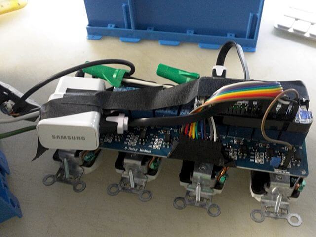
Pigtail solder the leads to the USB power adapter that you're gonna fit inside your box. This slightly big Samsung power unit just fits, and offers a lot of power out, but I've also used tinier format ones with success. Simply test that they give enough power by booting with them once (you did this earlier, right?). In this picture, I'm using 12-gauge solid wire, which is too heavy, and I ended up removing it and replacing it with lighter stranded gauge.

While I used my trusty soldering iron to make this connection, you could feasibly twist and wrap thinner wire and wrap in shrink wrap tubing for a suitable connection, considering how little jostling it might expect stuffed inside the box.

Note the shrink tubing just below the connection for sliding over the eventual soldiered connection. As this is polarized, either connection can go to either the hot or neutral lines, so I planned for how the USB was going to exit the adapter.

Final Hook Ups & Testing

Remember how I said to wait for doing the final hot hookups? We're at the final stretch.

Figure where your USB power adapter is gonna fit in your final arrangement, and then take the two pigtail leads you just created and trim and strip one to be bundled into the final group of hot wires. This should have the right four common hot leads (already attached to the relay), as well as the jumper lead from the other bundle, and you should also include the USB power lead as well as the incoming hot lead from the work box. It's a lot of wires (6), and I found they just fit in my electrician wire nuts, especially since some of the leads were stranded and not solid wire. That completes the basic hot wiring.

Attach the other USB power lead to the same common neutral line by attaching it to an empty white neutral screw terminal on any outlet.

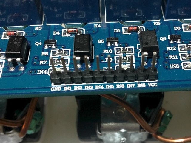
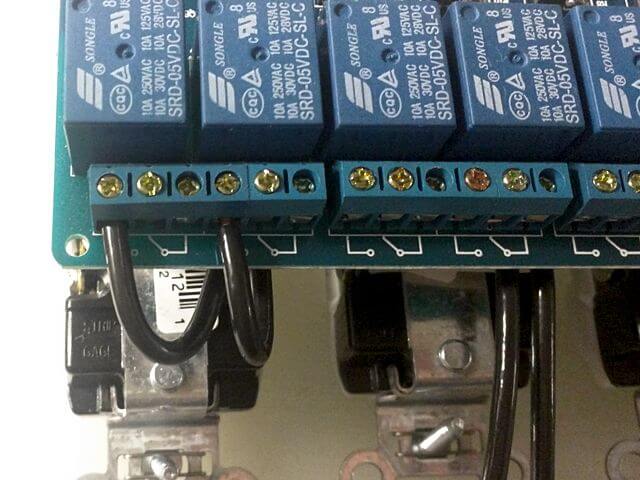
If you haven't already, hook up the USB power cable between the USB power supply and the Raspberry Pi, check the jumpers are all secure and seated on the Raspberry Pi and Relay board, and that all the wires are supposed to be where they are. If everything looks good and ready to go, you're ready for a live unboxed test.

You should run the Raspberry Pi headless, so unhook and HDMI and keyboards you might have attached. Plug in the box's power cord in the wall and look to the Raspberry Pi's LED to show you if it's booting. After some vigorous green blinking, you should once again see your device on your local subnet as http://shortname.local, and you can test each outlet and relay for functionality to your hearts content. When I tested, I noted I mis-wired and switched the 0 and 1 outlets to be opposite the others in the evens or odd. But every outlet worked without fail, no wires smoked, the breaker didn't blow and it hummed along nicely. Power down the Raspberry Pi again, (http://shortname.local/shutdown.php) and let's pack this into the work box.

Post Test Boxing

Pictured is our finished (and fully tested!) unit before being packed into it's box. We double-checked all the wiring and used masking tape to hold items in place while we squeezed it into it's tight space. You'll note the green wire nuts are tucked in the back, and hold an assortment of hot leads (with one stretching to the unmounted breaker on the far left.

After some gingerly squeezing and bending, we got it fully installed in the PVC work box, and screwed down all 4 outlets using the available screw mounts. Another live test showed nothing had changed from my previous perfect test, so I considered it a finished product! I could spring for a 4-up faceplate for the box to make a cleaner finish and alleviate concerns of fingers slipping between the outlets, but at $7 each, I can't suggest paying 10% more for a bit of unused plastic.

Finished Unit

Finished Unit

Last Thoughts

I can SSH into each Raspberry Pi (ssh pi@shortname.local) and set a crontab to turn on and off each relay as I need, or use the web interface. With some additional tweaking and a dynamic DNS name, I could turn it into a public API to turn on or off christmas or halloween lights, in combination with a video streaming service you could create a virtual attraction.

If you're looking for more finite command-line control, and need to setup CRON to switch the outlets, you can follow Two 'Sort Of' Tech Guys instructions and download their pre-written Shell Scripts (local mirror) to individually control each GPIO pin. Their code is easy enough to change to alter any GPIO pins, even though they pre-wrote for GPIO pins 4, 17, 18, 21, 22, 23, 24, 25, and 27. They also have alternate 'PowerControl' software worthy of checking out in full in their tutorial.

As the Raspberry Pi is a very powerful single-board computer, you can easily add services and connectivity to make it into a wifi capture portal, or simply design complex web interactions that have real-world effects! In conjunction with other Raspberry Pi's doing heat, light and humidity sensors, you could automate an urban farm to water, air, heat and light based on needs and some rudimentary programming. The possibilities are endless! I expect I'll end up making more of these as I start to put them to use! (hence my thorough documentation now...)

Below are the links to the very few sites I referenced when building my unit (to my specifications) and in this tutorial. Thank you to those below who inspired this project, and others linked in this tutorial. Thanks to TinyJPG for compressing our photos. Thank you for reading and I hope you find inspiration to do this project yourself!